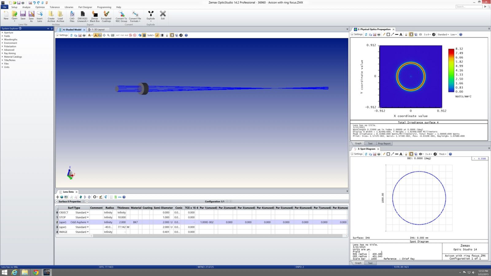
Zemax is an optical design program that is used to design and analyze imaging systems such as lenses, as well as illumination systems. It works by ray tracing-modelling the propagation of rays through an optical system. Zemax can model the effect of optical elements such as simple lenses, aspheric lenses, gradient index lenses, mirrors, and diffractive optical elements, and can produce standard analysis diagrams such as spot diagrams and ray-fan plots.
Zemax can also model the effect of optical coatings on the surface of components. It includes a library of stock commercial lenses. It can perform standard sequential ray tracing through optical elements, non-sequential ray tracing for analysis of stray light, and physical optics beam propagation.
The physical optics propagation can be used for problems where diffraction is important, including the propagation of laser beams and the coupling of light into sngle-mode optical fibers. Zemax’s optimization tools can be used to improve an initial optical design by automatically adjusting parameters to maximize performance and reduce aberration.
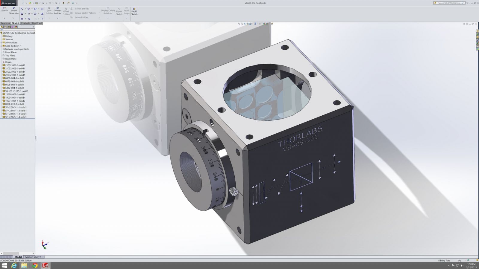
SOLIDWORKS
Mechanical Design Software
Building a model in SOLIDWORKS usually starts with a 2D sketch. The sketch consists of geometry such as points, lines, arcs, conics (except the hyperbola), and splines. Dimensions are added to the sketch to define the size and location of the geometry. Relations are used to define attributes such as tangency, parallelism, perpendicularity, and concentricity. The parametric nature of SOLIDWORKS means that the dimensions and relations drive the geometry, not the other way around. The dimensions in the sketch can be controlled independently, or by relationships to other parameters inside or outside of the sketch.
In an assembly, the analog to sketch relations are mates. Just as sketch relations define conditions such as tangency, parallelism, and concentricity with respect to sketch geometry, assembly mates define equivalent relations with respect to the individual parts or components, allowing the easy construction of assemblies. SOLIDWORKS also includes additional advanced mating features such as gear and cam follower mates, which allow modeled gear assemblies to accurately reproduce the rotational movement of an actual gear train.
Finally, drawings can be created either from parts or assemblies. Views are automatically generated from the solid model, and notes, dimensions and tolerances can then be easily added to the drawing as needed.